Piano Synthesizer & Loop Machine
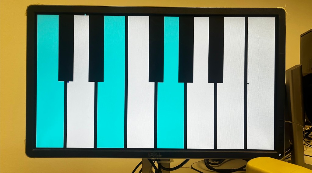
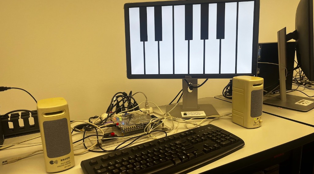
the goal was to build a musical instrument that converts a user input into an audio tone, modelled on a traditional piano. it has 13 unique tones mapped to 13 unique inputs.
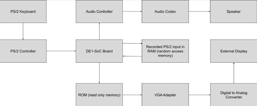
input is captured from a PS/2 keyboard, which passes through a PS/2 controller into the DE1-SoC board. the piano logic runs on the board and drives two outputs at once: a VGA display for visual feedback, generated from ROM through a VGA adapter and a digital to analog converter, and a set of stereo speakers through the audio controller and audio codec.
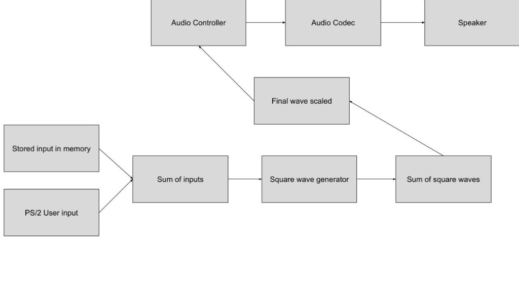
the tones are synthesized additively. every active input, whether it is live PS/2 input or a stored input read back from memory, is summed, fed into a square wave generator, and the resulting square waves are summed together. that combined waveform is then scaled into a final wave and passed to the audio controller and codec for playback.
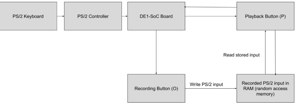
on top of live playing, the synthesizer records up to 10 seconds of user input. a recording button (O) writes the PS/2 input into RAM, and a playback button (P) reads the stored input back out of RAM into the DE1-SoC so it can be replayed at will. the capture lives in the board's on-chip memory, and the pipeline is designed to run with under 5 ms of audio latency inside the 50 MHz timing constraints.
in the future it could take an external MIDI keyboard controller in place of the PS/2 keyboard. the plan would be to use a microcontroller such as an arduino to receive MIDI input and convert it into a bitwise code or PS/2 signal that the FPGA can read.